Motto: A quote by Harry Truman.
Welcome, dear reader. I am today in a funny mood. This post is not serious. Or is it?
Speed Signs
Have you even wondered why don’t we use angular velocity and angular acceleration for track curving calculations and other track alignment design rules?
Or, even more than that, remove the speed entirely and refer only to angular velocity?
How interesting the speed signs would be!?!
Types of angular velocity
What kind of angular velocity, you rightly ask?
Well, the spin angular velocity is used in wheel movement calculations so it would be fair for the track to claim the other one, the orbital angular velocity. It would also make perfect sense. The centres of the curves we use for track design are far way, not close to the vehicle centre of mass (most of the time – let’s leave it like this, for now!). So, Orbital Angular Velocity is then.
Orbital angular velocity calculations for railway (and road?) alignment design
How will this work?
If an object moves with constant angular velocity φ it will describe a circular arc of radius R.
Let’s compare two such objects. An object A moves on an arc of radius RA and the other, object B, on an arc of radius RB . At every second both cover an arc length corresponding to an angle α. The angular velocity is then φ = α /s
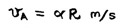
The object A will describe in one second the arc AA’

So the speed of this object, in m/s can be calculated as:
Because it moves on a circular trajectory, this object will experience a centripetal acceleration (and if the object is a vehicle, the people inside will experience an inertial centrifugal acceleration) which we can easily calculate:
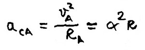
I’ll refer to centrifugal acceleration from now on just because all the other posts I have on this blog on cant, cant deficiency, or rates of change for these, are all referring to centrifugal and not centripetal acceleration. There is an interesting article in one of the latest PWI journal debating the difference.
Moving on … The object B, is placed at ar RB distance from the centre O. And we assume for now this radius to be double the value of RA. RB = 2RA
Same math as above – arc length:
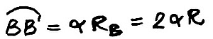
Which comes double in length to the one on which the object A is moving. Twice the distance in a second gives us twice the speed:

… and because we move on a circular arc, inside the object/vehicle B can be experienced twice the lateral acceleration experienced in object/vehicle A:

Angular acceleration?
Why complicate the things? I leave that to you, dear reader. let’s stay with constant angular velocity.
How can we use this?
Let’s look into a real life example.
For an angular velocity of 1.025°/s, a vehicle moving on a 1000m radius will have a speed of 40mph. If it is running on an uncanted railway track of normal gauge (essential to mention this, see?!) it will experience a cant deficiency of 49mm (or it’s equivalent uncompensated lateral acceleration).
The other vehicle, moving on a 2000m radius, will have a speed of 80mph, and a cant deficiency of 98mm (if the track is not canted).
Same velocity, bigger the radius, bigger the cant deficiency. Makes perfect sense!

And this is just a quick, back of the envelope calculation to answer the question:
Why don’t we use angular speed and acceleration for railway track curving calculations?

Oh, indeed Master. There is another! To be continued…
May the 4th be with you!
Discover more from A railway track blog
Subscribe to get the latest posts sent to your email.


