Where the author eloquently discusses the versine formula and the accuracy loss implied by ignoring a historically insignificant term of its equation, demonstrates an easily replicable CAD check of this inaccuracy, and reveals the EXACT versine formula. The author also debates the precision of the equivalent radii calculated based on versine differences, proving its inherent lack of accuracy, and points out to a “Swiss method of bending” for a more accurate calculation of the equivalent turnout radius for S&C. 3.14.
Products of their time
Many of the formulas we use in engineering today were developed decades ago – 40, 60, even over 100 years in the past.
Some of these formulas are exact, fully based on scientific principles, and have remained unchanged because they remain valid.
Others are approximations—practical solutions devised by engineers to solve specific problems. These were designed to be easy to apply and accurate enough for the needs of their time.
Some of these approximate methods have been abandoned as technology has advanced.
Others have been revised and refined to meet the accuracy and precision required in modern engineering.
Very few have been adopted to new procedures and processes, forgetting their initial assumptions and overlooking their limitations.
One such example is the versine formula.
Originally used for realignment calculations – Hallade and others such methods – the versine formula and other calculations based on it, the equivalent radius formula being the main one, have been adopted in track alignment design, for plain line and especially S&C, calculating radii with very high precision, forgetting the inaccuracy these formulas inherently hide.
The Versine Formula
The versine formula is probably the second most used railway track calculations. The versine is also the most visited page on this blog – both by humans and non-human readers.
I’ll repeat here briefly what the versine formula is all about.

For the drawing above, where we measure the versine, v (BD), on a chord of length c (AC), for a circle of radius R, we can apply the Altitude Theorem, as below:

if we calculate this further, we get on the right side a term v², which is, in this context, too small relative to the other terms.
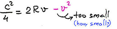
For example, for a chord of 20m and a 200m(ish) radius this equation will look like this:
100 = 100(ish) – 0.0625
So, even for this very tight radius, the squared versine has a very small impact on the calculation – it is only 0.06% relative to the rest. It is hence justified to ignore this value, in the context for which this formula was initially defined.
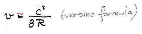
With the v² term ignored, we get:
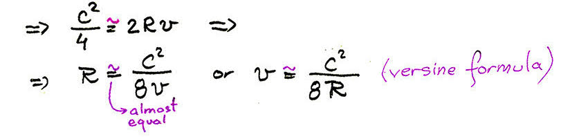
The resulting formulas allow to calculate the versine based on the radius and chord, or calculate the radius R, based on a measured versine and a chord length.
For Hallade and other realignment calculations, these formulas were an accurate enough approach, considering the accuracy implied by versine measurement and the way the track was corrected using the calculated slues (slews).
These formulas were the efficient product of their time. Now we have computers, CAD, we don’t do Hallade calculations as much, but we still calculate radii using versine based formulas, to millimetre precision.
Let’s test the versine formula using our modern tools.
A versine check in CAD
We can easily check the versine formula by following these steps, using a CAD software:
- Draw a chord AC of a given length C
- From the middle, D, of this segment, perpendicular on it, draw the versine v (a new segment -BD)
- Draw a circular arc passing through the points A, B, C
- Measure the radius of the arc ABC
See stages animation below:
Please, dear reader, I strongly encourage you to check my findings for yourself.
I will label Rv the value of the Radius calculated using the versine formula, to make the difference to R, the actual radius , measured in CAD.
Case 1. C=20m v=20mm
For a chord c=20m and a versine of 20mm, the measured radius is R=2500.010m
If we calculate the radius using the versine formula we get Rv=2500.000m
The difference between the two radii is 10mm.

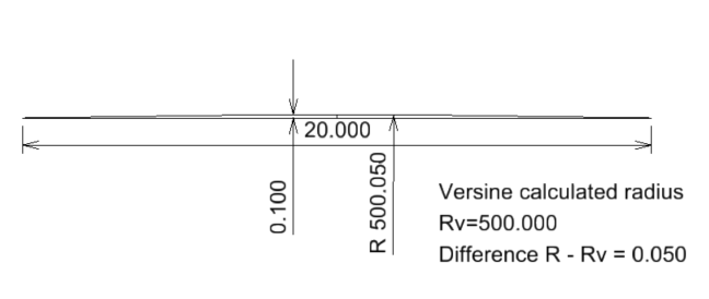
Case 2. C=20m v=100mm
For a chord c=20m and a versine of 100mm, the measured radius is R=500.050m
If we calculate the radius using the versine formula, we get Rv=500.000m
The difference between the two radii is 50mm.
Case 3. C=20m v=500mm
For a chord c=20m and a versine of 500mm, the measured radius is R=100.250m
If we calculate the the radius using the versine formula we get Rv=100.000m
The difference between the two radii is 250mm.

You probably noticed a pattern already and might be inclined to think this is due to the chord length of 20m, so let’s change that to a random value. Same for versine.
Case 4. C=23.745m v=1.254m
For a chord c=23.745m and a versine of 1254mm, the measured radius is R=56.830m
If we calculate the radius using the versine formula, we get Rv=56.202m
The difference between the two radii is 627mm.

For turnout designs, we bend curves that have a versine equal to the track gauge, so let’s test one.
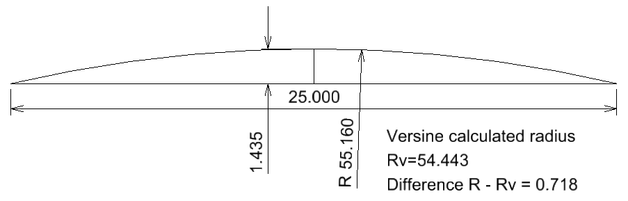
Case 5. C=25m v=1435mm
For a chord c=25m and a versine of 1435mm, the measured radius is R=55.160m
If we calculate the radius using the versine formula, we get Rv=54.443m
The difference between the two radii is 0.718mm.
This radius is surely too tight for railway track. So let’s test it on a longer chord (close to a 2x(L2+T)).
Case 6. C=65m v=1435mm
For a chord c=65m and a versine of 1435mm, the measured radius is R=368.749m
If we calculate the the radius using the versine formula we get Rv=368.031m
The difference between the two radii is 0.718mm.

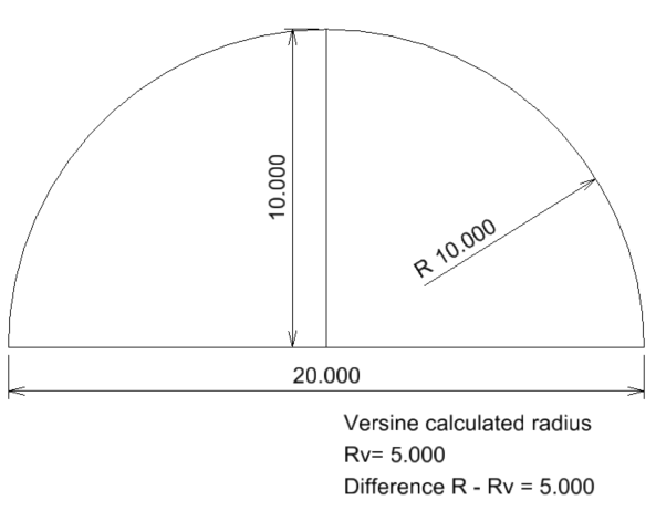
Case 7. C=20m v=10m
For a chord c=20m and a versine of 10m, the measured radius is R=10m
If we calculate the radius using the versine formula, we get Rv=5m
The difference between the two radii is 5m.
Versine turbulence?
You can do this check for any combination of chord and versine lengths and you will always notice that the CAD measured radius is slightly or significantly different from the radius calculated with the versine formula.
That difference is always half of the versine value!
What is the explanation for this? What is wrong?
The exact versine formula (© PwayBlog)
Nothing is wrong!
Let’s return to the last accurate formula we discussed above, just before ignoring v² because it is too small, and divide that equation by 2v:

we will get a Radius as function of (v) formula, adjusted by v/2 (no matter the chord length):
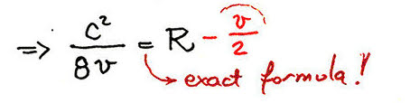
This is, dear reader, the EXACT formula that defines the relation between chord, radius, and versine.

That is why, in all the CAD checks, the measured value of the radius does not match the one calculated using the versine, and varies for all, no matter the chord length, by half of versine.
So what?
The difference between the approximate and exact versine formula is insignificant in real terms, on site.
However, the above presented demonstrates that any radius calculated using the versine formula, or any other derived from it, is likely to be half-a-versine inaccurate.
Yes, dear reader, all the radii we calculate to millimetric precision using this formula are likely to be wrong beyond the first decimal.
The major impact is on all the equivalent radius values calculated for curved S&C, using the versine bending formula, based on versine differences:
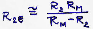
Because the turnout bending is for a curve that has an initial versine equal to the gauge (turnout route rail relative to mainline straight), it is very likely that the accurate equivalent radius Re to be off by approximately half a gauge. In this case the inaccuracy will be also influenced by the way we measure the lengths involved in the bending and by other criteria used to define the curvature of the bent turnout.
This inaccuracy is one of the reasons we need to allow minute but noticeable sometimes bearing changes in a curved turnout geometry, if that turnout is bent using the approximate, versine based, equivalent radius formula.
You wonder probably if there is a more accurate way of turnout bending, one that avoids bearing changes on the turnout route?
A Swiss bending method?
Searching the 2025 internet for an answer to this question, you might discover dear reader, that most of the national or regional track alignment standards are now behind well guarded walls, not publicly available, hidden to the human or artificial agents mining for knowledge.
There is fortunately one track alignment standard available online that gives some light to an alternative (well-known) bending method:
“Directives Techniques pour Tram – 4. Geometrie de la Voie.” 2013 – Transports Publics Genevois (TPG) Geneva, Switzerland. (Technical Directives for Tram – 4. Track Geometry).
This Swiss tram track standard presents a turnout bending method that is not based on versine but on the tangent length (see page 5)

The Swiss turnout bending method quoted by the standard is using an accurate formula, using the tangent length t, related to the turnout crossing angle.
We’ll see in a future PwayBlog article how this formula was defined and what Bloss had to say about it. Bloss the engineer, not the transition curve. Bloss, the professor who invented the Bloss transition curve.
(Later edit … if I can find Bloss’s quote.)
Post scriptum:
If you find this blog interesting, I strongly encourage you, dear reader, if you are human, to subscribe to my blog.
One day I might decide to hide from the artificial miners visiting this website some of the things I write.
It is free. The only thing this form does is send an email to the blog subscribers as soon as I write something.
Discover more from A railway track blog
Subscribe to get the latest posts sent to your email.


I don’t trust spreadsheets when I can draw and measure directly.
Draw it and measure it.
LikeLike
Using simple trigonometry, I developed excel sheet to cross check the results which matches except case 5 and case 6 where there is typo. Units should be metre. This excel sheet is self-explanatory.
Excel gives results in few second. It took less than a minute check the calculation of all the seven cases.
Wherever possible I prefer to use excel to cross check the calculation done in cad because it is quick to check. Sometimes I verify my excel calculation from cad.
Screen shot of excel sheet is attached.
Please review and let me know if there is any mistake.
[cid:a3a306dd-e7c6-4d15-b3ec-fd971034b8ae]
LikeLike