Versine turnout bending
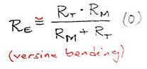
The classical and probably the most used method of turnout bending is based on the equivalent radius formula (0), derived from the assumption that the versine of the equivalent radius RE is equal to the difference between the versines of the mainline radius RM and the turnout radius RT, respectively.
But, as discussed in the previous article, the versine formula is approximate; sufficiently exact for Hallade versine calculations, but potentially less accurate for radii calculations of CAD designed S&C geometry.
Tangent turnout bending
One of the methods to reduce the impact of these approximations on the turnout bent equivalent radius is based on the crossing angle, α. This angle is also used for the standard definition of the turnout radius.

In my previous article, I included this snapshot from a Swiss tramway standard, presenting this more accurate method of turnout bending:
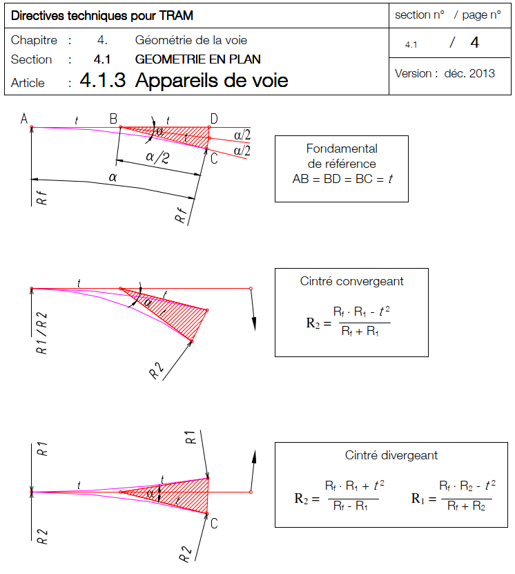
This alternative method of calculating the equivalent radius of the bent turnout route uses the tangent length t, for the circular turnout route of radius RT and crossing angle α.
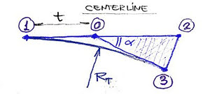
The calculation presented here is defined on track centerline geometry.
The turnout is schematically defined by the points 1 (in this case, the origin of the switch) – 0 – 2 – 3. 1 and 3 are the tangent points for the circular turnout of radius RT.
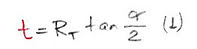
The length t of the tangent is (1)
Considering a similar flexure bending of this turnout, we will get on the centerline mainline route the radius RM and on the turnout route an equivalent radius RE. The bending of the mainline route is defined by the tangent angle β.
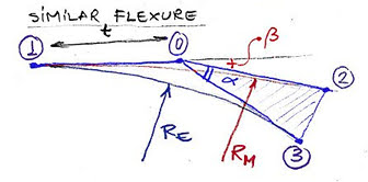
For these two centerline radii we can calculate the value of the tangent t.
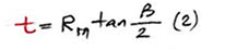
For the mainline, we have the tangent angle β; the tangent, t, is calculated as
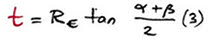
For the bent turnout route, the tangent angle is (α+β). The same tangent, t, is, in this case
Recalling old trigonometric rules, the tangent of the sum is not quite the sum of the tangents, but
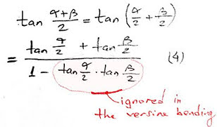
And we see here a term ignored in the versine bending rule.
In this formula (4), we can replace the tangents based on (2) and (3).
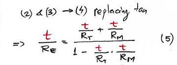
and furthermore, by reversing this fraction and doing some simplifications, we get (6)
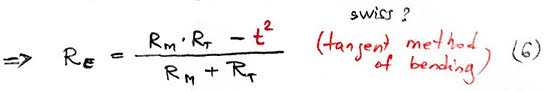
This is the similar flexure formula for the tangent method of bending turnouts, quoted in the above Swiss standard.
If the bending is contraflexure, the formula (6) becomes (6′)

As these tangent based formulas are not ignoring the term quoted in formula (4), they are more accurate than their versine method equivalents.
Precise? Accurate? Exact?
But are these formulas exact? Is this method exact?
If you will do the check I mentioned in an older article, you’ll find the answer.
Not yet the explanation.
For that, my dear reader, I need to take you back in time, and discuss about long forgotten things, perhaps even about the subtle difference between the curved turnout (as in that turnout designed from first principles to have both branches on curves) and a curved turnout (that unit which is designed with mainline on straight and then bent using offsets to a curved layout).
But that is a story for another time!
(To be continued)
Discover more from A railway track blog
Subscribe to get the latest posts sent to your email.


None. Thanks for your comment. I forgot to mention the so wrongly called “Swiss” and “German bending”. I will write over the weekend the explanation for this. Sorry!
LikeLike
What is the difference between this Swiss method and the German method of bending, please?
LikeLike